LS contact line measurement

Introduction:
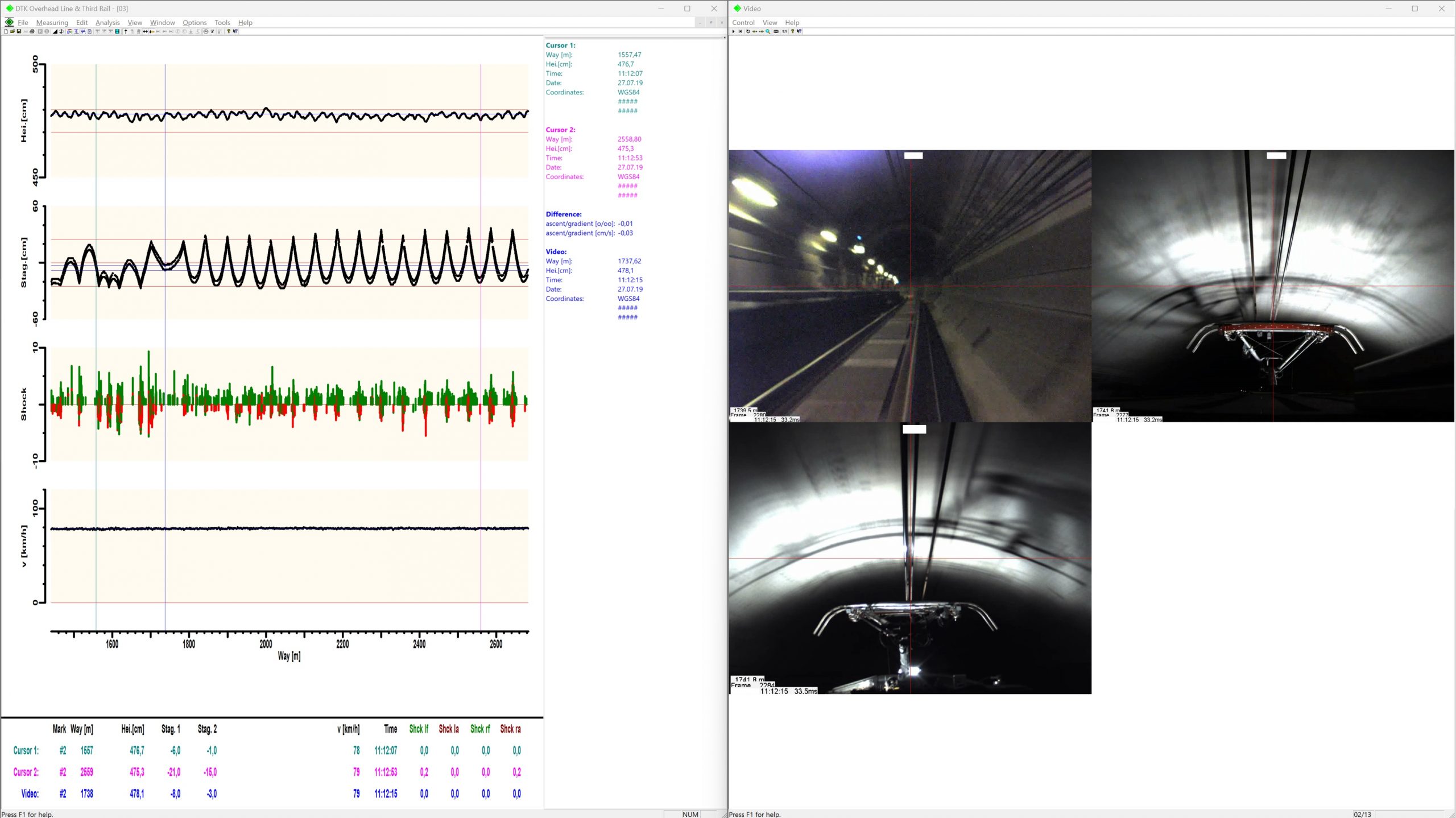
Proper overhead contact wire positioning is crucial for the smooth operation of railways. The wire must be aligned such that the train’s pantograph can reach it without issues, ensuring uninterrupted power supply. Incorrect or faulty wire positioning can lead to energy losses, operational disturbances, and, in the worst case, accidents. To ensure that the wire positioning meets requirements, acceptance tests are conducted on newly built catenary systems in various rail systems such as metros, railways, and trams. For this, the DTK “Position-Impact” measuring system is used, which can also be adapted as a permanent monitoring system.

Measuring system:

The DTK “Position-Impact” system is specially developed for troubleshooting in the catenary network. It captures the contact wire height, rise/decline, lateral position (zigzag), impacts (horizontal and vertical) affecting the pantographs, speed, and the track position of the measurements (GPS coordinates and track meters). Optionally, the lateral inclination of the car body for determining the static zigzag position of the wire, current and voltage, and temperature (thermography measurement) can also be recorded.

Advantages:

The DTK “Position-Impact” system helps to avoid downtime by timely identifying problem areas, enabling derived repair work from the measurement data. It can also determine the causes of transverse grooves in the carbon strips and the wear pattern of the carbon strips. The impact detection is so sensitive that even the slightest running irregularities of the carbon strips can be determined. Impact detection is performed using 2 sensors attached to the carbon strips. It’s possible to record the electrical current transmitted over the carbon strips (including recuperation). Thermography measurements can simultaneously determine the temperature at the contact point between the contact wire and the carbon strip. Additionally, the electrical voltage of the contact wire can be captured at any position in the network, as well as UV arcing
at the contact point between the carbon strip and wire.

Evaluations:

User-friendly software helps identifying significant phenomena, such as excessive lateral positioning of the overhead line on the carbon strip or sections with insufficient zigzag. The software also allows for selecting specific sections and playing the corresponding video sequences of the panoramic view and the contact between pantograph and wire. GPS data recording enables a comfortable display of deviations in a map view. Exporting data to own databases or for further use is also possible.

By combining wire position measurements and track measurements, interactions between the track and overhead line can be identified. For instance, high-speed installations or curves can cause vibrations and jolts affecting the wire position. By analyzing data from the “Position-Impact” system and track measurements, such correlations can be recognized and evaluated.

The “Position-Impact” system is suitable not only for acceptance testing of new overhead line installations, but can also be used as a permanent monitoring system. It allows for continuous monitoring of the wire position and carbon strips, thus helping to detect problems early and reduce downtime.

In summary, the “Position-Impact” measuring system plays a vital role in inspecting and monitoring overhead line installations in various rail systems such as metro, railway, and tram. It enables precise measurement of wire height, rise/decline, lateral position (zigzag), and impacts, as well as optionally current and voltage, UV arcing and temperature. The user-friendly software assists in data analysis and interpretation, while GPS data enables a comfortable display of deviations in a map view. By combining with track measurements, mutual influences of the track and overhead line can be captured.